Composite double-bridge Kralupy
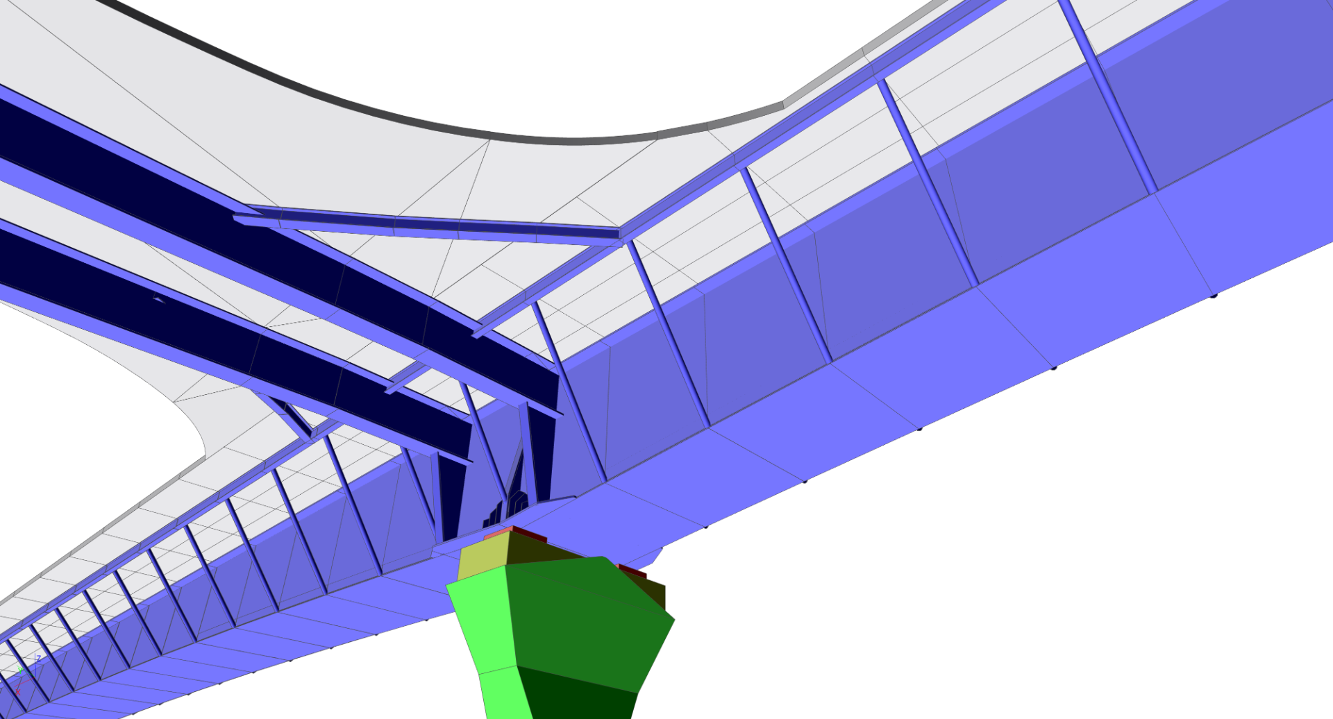
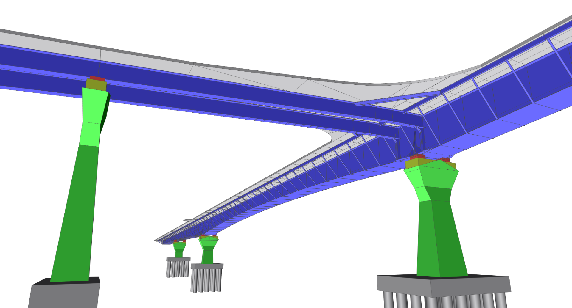
Special bridge project near Kralupy, Czech Republic, consists of 2 bridges (main bridge and ramp) that are connected on the 1st intermediate pier of the main bridge. The main bridge is a double-composite bridge of 4 spans 101+147+75+55 m (total superstructure length is 373,75 m). The bridge has width varying between 16,6 m to 18,35 m. On the 1st intermediate support of the main bridge is connected in the perpendicular direction a 306,125 m long ramp with 6 spans 50,425+55+50+45+42+40+23 m and width 11,35 m. Both bridges create an unprecedented junction. The model was created for basic design and expected construction beyond year 2020.
The main bridge is of steel box cross-section with varying height and with top concrete slab and also bottom concrete slab in the vicinity of supports. This structural system is called double composite and provides greater stiffness than a continuous composite bridge without the bottom slab. The bottom slab is also very cheap to do, as its formwork is directly the steel box girder. The bottom concrete slab provides needed stiffness during the construction process, which is planned to be the free cantilever erection from both intermediate piers adjacent to the main span of the bridge.
The ramp is a traditional multi-span composite bridge with double I cross section and with constant height. The erection method chosen for the ramp is incremental launching of completed steel structure from its abutment and after welding to the main bridge, the concrete deck is casted. Both bridges have specifically designed shape of piers.
This was the team's first major project in SCIA Engineer using parametric modeling in Excel rather than direct software entry. Both structures feature significant longitudinal inclination and repetitive geometry. The main bridge's box cross section has parabolically varying height with evenly distributed transverse braces. Bridges were defined in Excel and imported via Table Input. The preliminary model was complete within 2 days. Additional components were added manually, including junction details, a lookout platform, bearing details, piers, and foundations. Piers were approximated by column elements and heavily reinforced. Load cases, including repetitive traffic loads, were also composed in Excel.
Reference: Created exclusively for VPU DECO, 4/2017